
CMS combustion management system
Modular burner and plant control that scales from small industrial burners to large installations
LAMTEC · CMS
- SIL3 · CE · UL
- ≤ 10 actuators
- Modbus TCP
- CODESYS
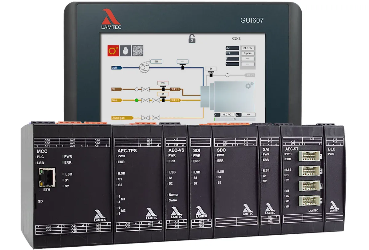
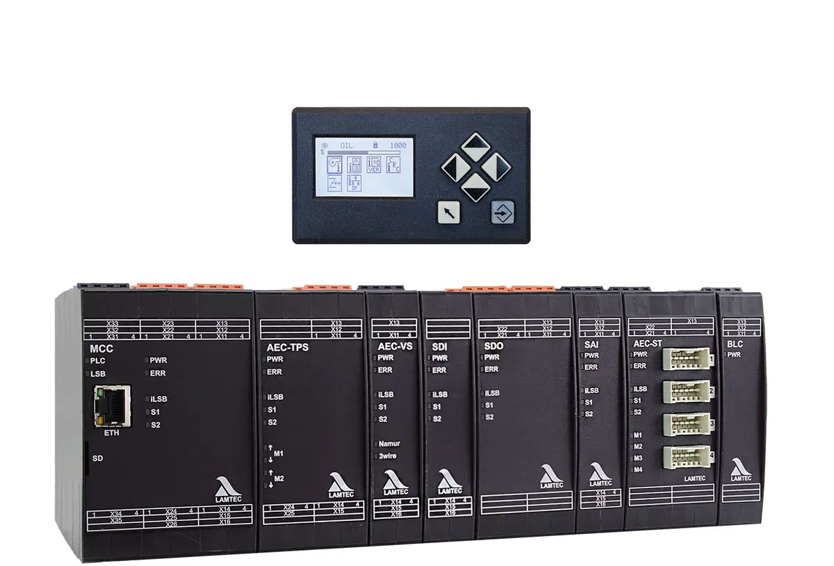
CMS is a combustion management system that brings burner sequencing, electronic fuel-air ratio control and flame monitoring together in modules. Starting from the MCC main module, actuator, speed and input/output modules are added so that the system matches the plant, from a simple industrial burner to a demanding process application. The modules are linked by the fail-safe LAMTEC system bus.
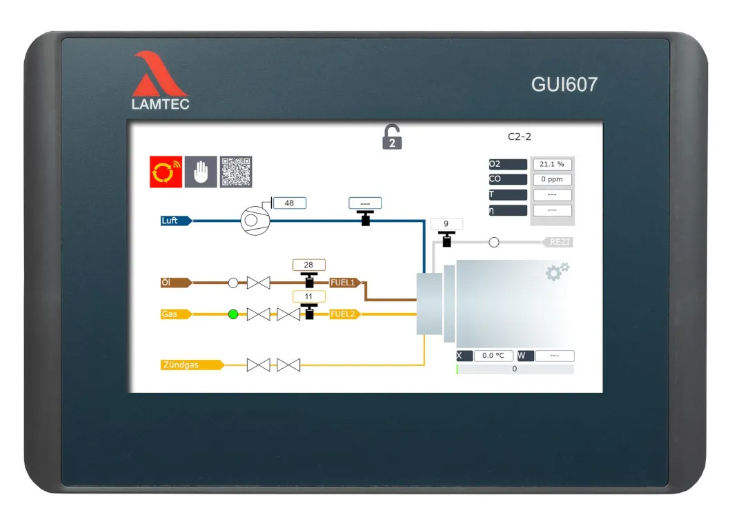
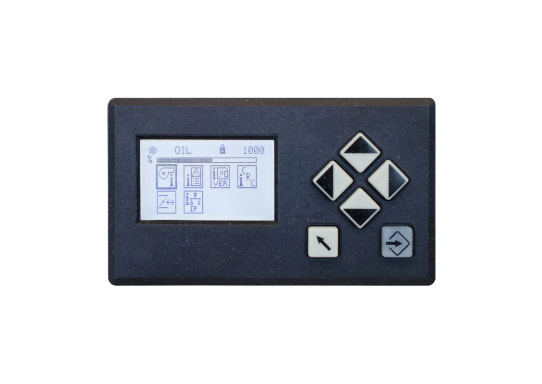
Modbus TCP comes as standard; PROFIBUS DP and PROFINET are added with extra modules. The integrated CODESYS soft PLC handles control tasks that are not safety-related, so no separate PLC is needed. For operation, choose the economical UI400 or a 7, 10 or 15-inch GUI touch screen. The system holds CE, UL and SIL3 approvals.
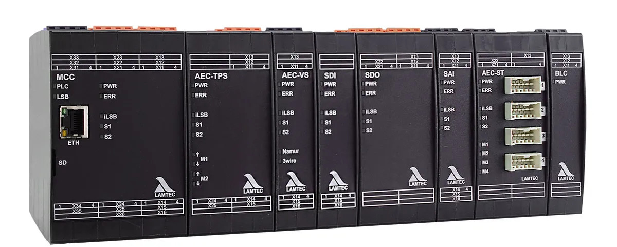
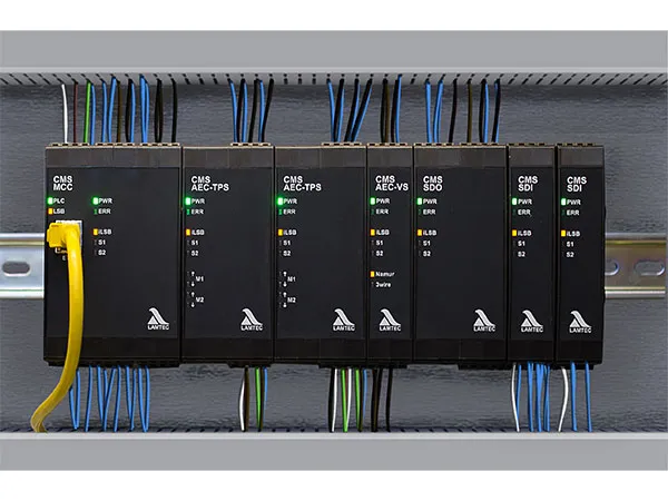

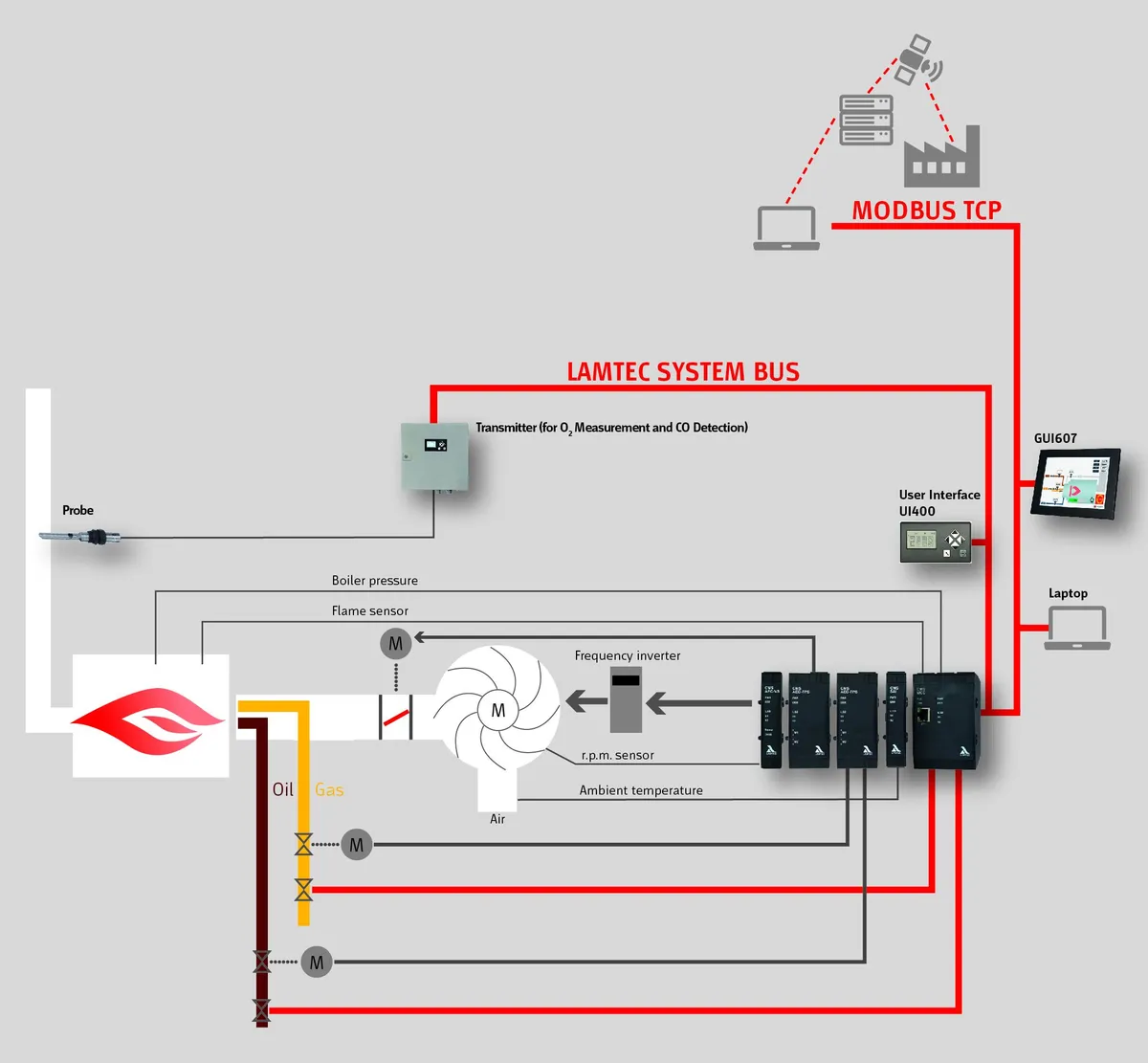
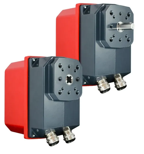
CMS combustion management system
- Up to 10 fuel-air ratio channels using TPS actuators, frequency inverters or 4–20 mA positioners
- Up to 60 fail-safe digital inputs, 41 fail-safe digital outputs and 18 analogue inputs, all freely assignable
- Built-in flame monitoring (ionisation electrode or FFS07/FFS08 optical sensor) and up to 4 valve leakage tests
- O₂ trim control and adaptive CO/H₂ combustion optimisation (SIL2)
- Fixed-ratio mixed firing of up to 4 fuels at once, with up to 16 curve sets
- Largely language-neutral operation using symbols, plus an integrated fault indicator system
- Protection against unauthorised access and data encryption
- Modules can sit centrally in the control cabinet or be distributed across the plant
CMS combustion management system
MCC burner module
Carries the burner sequencer together with flame monitoring and valve leakage testing, plus all communication interfaces. It has 12 fail-safe digital inputs, 9 fail-safe digital outputs (2 A each, 8 A in total at most), a firing-rate input for 4–20 mA, TPS or potentiometer signals, a 4–20 mA firing-rate output, Modbus TCP over Ethernet and a CODESYS soft PLC. Inputs for FFS07/FFS08 or ionisation are optional; five input/output voltage versions are available.
AEC-TPS actuator module
Drives two 3-point step TPS actuators and monitors their position through 5 kΩ potentiometers. Versions for 120 V AC and 230 V AC are available; one system accepts up to 5 modules. TPS actuators from 6 to 200 Nm are offered for CMS.
AEC-VS speed module
Controls the frequency inverter of the combustion air or recirculation fan, or devices driven by 4–20 mA such as pneumatic actuators. Feedback comes from a NAMUR sensor, a 3-wire sensor or a 4–20 mA signal; a digital output signals that the fan is running and a digital input reports an inverter fault. A system can use up to 10 modules.
SDI safety input module
Provides 8 freely configurable fail-safe digital inputs, in 24 V DC, 120 V AC and 230 V AC versions. A system takes up to 6 SDI modules, for a maximum of 60 digital inputs in total.
SDO safety output module
Provides 8 freely configurable fail-safe digital outputs rated at up to 2 A each, in 24 V DC, 120 V AC and 230 V AC versions. A system takes up to 4 SDO modules, for a maximum of 41 digital outputs in total.
SAI analogue input module
Offers 3 fail-safe or 6 non-safety analogue inputs, or a mix of both, usable as 4–20 mA, Pt100 or Pt1000 inputs, plus two pulse inputs for fuel meters. With up to 3 modules, a system reaches 9 fail-safe or 18 non-safety analogue inputs.
AEC-ST stepper motor module
Controls four 662R5X stepper motors, the same type used with BT300, with torques of 0.8, 1.2, 3 and 9 Nm. A system can use up to 2 AEC-ST modules.
BLC bus link module
Extends the internal bus by cable so that CMS module groups installed in different places can work together; each bus segment can be up to 70 m long. The active BLC sits at the receiving end of a line, opens a new segment and needs a 24 V DC supply. The passive BLC works as the transmitter at the start of a line and needs no separate supply.
Key specifications
| Specification | CMS |
|---|---|
| Fuel-air ratio channels | ≤ 10 |
| Inputs / outputs | ≤ 60 DI · ≤ 41 DO · ≤ 18 AI |
| Fuels | ≤ 4 (fixed-ratio mixed firing) |
| Safety integrity level | SIL3 |
| Interfaces | Modbus TCP · PROFIBUS DP, PROFINET (optional) |
| Flame detection | Ionisation · FFS07 / FFS08 · digital input (F200K, F300K) |
| Supply voltage | 24 V DC ±20 %, SELV |
| Degree of protection | IP20 |
| Ambient temperature | -30 … +70 °C |
Approvals and standards
- CE declaration of conformity (2014/35/EU, 2014/30/EU, 2014/68/EU, (EU) 2016/426, 2011/65/EU)
- EU type examination certificate — 2014/68/EU, Module B (pressure equipment)
- EU type examination certificate — (EU) 2016/426 (gas appliances)
- SIL3 — DIN EN 61508
- DIN EN 298
- DIN EN 1643
- DIN EN 12067-2
- DIN EN 13611
- ISO 23552-1
- DIN EN 50156-1
- DIN EN 50156-2
- UL 60730-2-5 (US)
- UL 60730-1 (US)
- CSA C22.2 No. 60730-2-5 (CA)
- CSA E60730-1 (CA)
- Eurasian conformity (EAC) — TR CU 016/2011
Accessories
- GUI607 colour touch screen: 7-inch, 800 × 400 pixels, IP65 at the front
- GUI610 colour touch screen: 10.1-inch, 1280 × 800 pixels, IP65 at the front
- GUI615 colour touch screen: 15.6-inch, 1366 × 768 pixels, IP65 at the front
- UI400 user interface: graphic display with symbols, connected over LSB at up to 500 m from the MCC
- Additional cover that raises the UI300 and UI400 panels to IP65
- Modbus TCP / PROFIBUS DP gateway for a PROFIBUS DP connection
- EBM412 fieldbus module for a PROFINET IO connection
- PSU2415 … PSU24150 power supply units: 100…240 V AC in, 24 V DC out, 15–150 W
- CMS PC software for configuration, backup and commissioning (basic, commissioning and expert versions)
Documents
- Data sheet · MCC (opens in a new tab)
- Data sheet · AEC-TPS (opens in a new tab)
- Data sheet · AEC-VS (opens in a new tab)
- Data sheet · SDI (opens in a new tab)
- Data sheet · SDO (opens in a new tab)
- Data sheet · SAI (opens in a new tab)
- Data sheet · AEC-ST (opens in a new tab)
- Data sheet · BLC aktive (opens in a new tab)
- Data sheet · BLC passive (opens in a new tab)
- Data sheet · GUI607 (opens in a new tab)
- Data sheet · GUI610 (opens in a new tab)
- Data sheet · GUI615 (opens in a new tab)
- Data sheet · UI400 (opens in a new tab)
- Data sheet · UI300 / UI400 Cover IP65 (opens in a new tab)
- Operating manual (opens in a new tab)
- Product catalogue (opens in a new tab)
- Product catalogue (opens in a new tab)
- EU Data Act information (opens in a new tab)
More products in this group
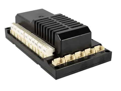
BT300 burner control unit
Compact burner-mounted unit that pairs fuel-air ratio control with a burner sequencer
- ≤ 3 actuators
- Burner-mounted
- SIL3 (BT331, BT341)
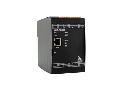
MCC-BC400 burner sequencer
Configurable burner sequencer for gas-fired, oil-fired and dual-fuel burners
- SIL3 · CE · UL
- Gas · Oil · Dual fuel
- Modbus TCP
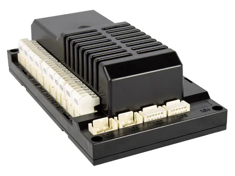
BC300 gas burner sequencer
Burner sequencer for industrial gas burners in thermal process plants, approved for intermittent and continuous operation
- SIL3 · CE
- Intermittent · Continuous
- High-temperature operation > 750 °C
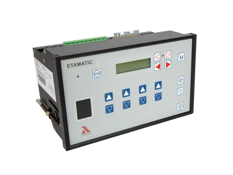
ETAMATIC compact burner control unit
Compact unit that combines electronic fuel-air ratio control and a burner sequencer in one housing
- ≤ 4 actuators
- SIL3 · CE
- Gas · Oil
Let's choose the right product for your project together
Tell us about your plant and what you need, and our engineers will recommend the right solution.